150mm 45° Ceiling Penetration (Option 2) Free Standing Woodfire Flue Kit Installation Instructions
../Installation Guides/150mm 45° (Option 2) Free Standing Wood Fire Flue Kit Installation Guide
WARNING: THIS FLUE KIT HAS BEEN MANUFACTURED IN ACCORDANCE WITH AS/NZS 2918:2001 AND TESTED TO APPENDIX F. TO ENSURE ITS SAFETY THIS FLUE KIT MUST BE INSTALLED AS OUTLINES IN THESE INSTRUCTIONS AND THE APPROPRIATE REQUIREMENTS OF THE RELEVANT BUILDING CODE OR CODES WOOD FIRE AND FLUE CLEARANCES FROM COMBUSTIBLE WALLS MUST BE IN ACCORDANCE WITH WOOD FIRE MANUFACTURER'S SPECIFICATIONS AND AS/NZS 2918:2001. THESE INSTALLATION INSTRUCTIONS ARE FOR TESTED APPLIANCES ONLY.
CAUTION: MIXING FLUE SYSTEM COMPONENTS FROM DIFFERENT SOURCES OR MODIFYING THE DIMENSIONS SPECIFICATIONS OR COMPONENTS MAY RESULT IN HAZARDOUS CONDITIONS. WHERE SUCH ACTION IS CONSIDERED, THE MANUFACTURER SHOULD BE CONSULTED IN THE FIRST INSTANCE.
CAUTION: IT IS THE RESPONSIBILITY OF THE INSTALLER TO ENSURE THAT THE INSTALLATION OF THIS FLUE KIT COMPLIES WITH THE AS/NZS 2918:2001, THE APPLIANCE MANUFACTURER'S SPECIFICATIONS FOR FLUE PIPE SHIELD AND CEILING PLATE AND THAT THE RELEVANT BUILDING CODES AND ADHERED TO.
BENDS AND EXTENSIONS TO THE LENGTH OF A FLUE SYSTEM ARE PERMITED (AS/NZS 2918 4.1)
WARNING: THE EXACT ANGLE OF THE CEILING MUST BE ACCURATELY DETERMINED TO ENSURE THAT THE CEILING PLATE OR THE CEILING TRIM PLATE ARE MANUFACTURED TO THE CORRECT DIMENSIONS.
- Locate Wood Fire in its proposed position and mark a point on the ceiling that is directly above the centre of the Wood Fire’s flue spigot. Check that the Wood Fire’s location allows the OUTER CASING to clear all structural roof timbers.
- Check that the proposed hole for the OUTER CASING will be clear of structural timber and then mark out for a hole in ceiling 250mm x 355mm and then increase the top line by approx. 15mm before cutting.
- Using a liquid glue fit 2 pieces of 100mm x 50mm timber along the long edges of the hole, make these pieces as long as possible and screw fix through the ceiling material taking care to conceal the screws behind the ceiling plate cover area.
- Cut a hole in the roofing to suit the roof flashing, the timber, which has been fixed to the upper edge of the ceiling, must be the further secured to the roof timber or roofing iron.
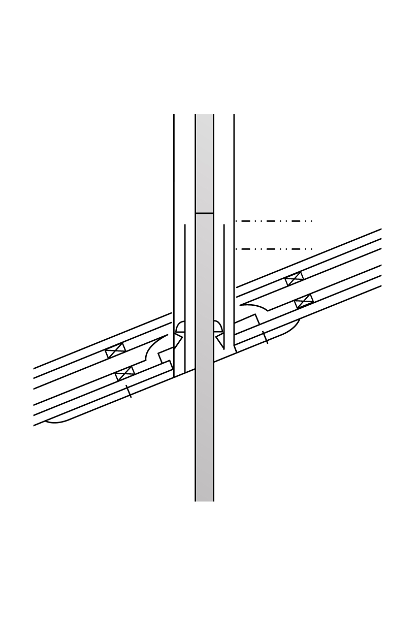
- The 225mm DROP CASING UNIT can now be fixed in position to the timber and the trim plate fitted to the ceiling. Ensure that the heads of the fixings will not stop the 250/200 OUTER/INNER CASINGS from fitting into the DROP CASING UNIT.
- The 250/200 OUTER/INNER CASING can then be lowered into the DROP CASING UNIT to rest on the internal swage ring. Riveting is also recommended.
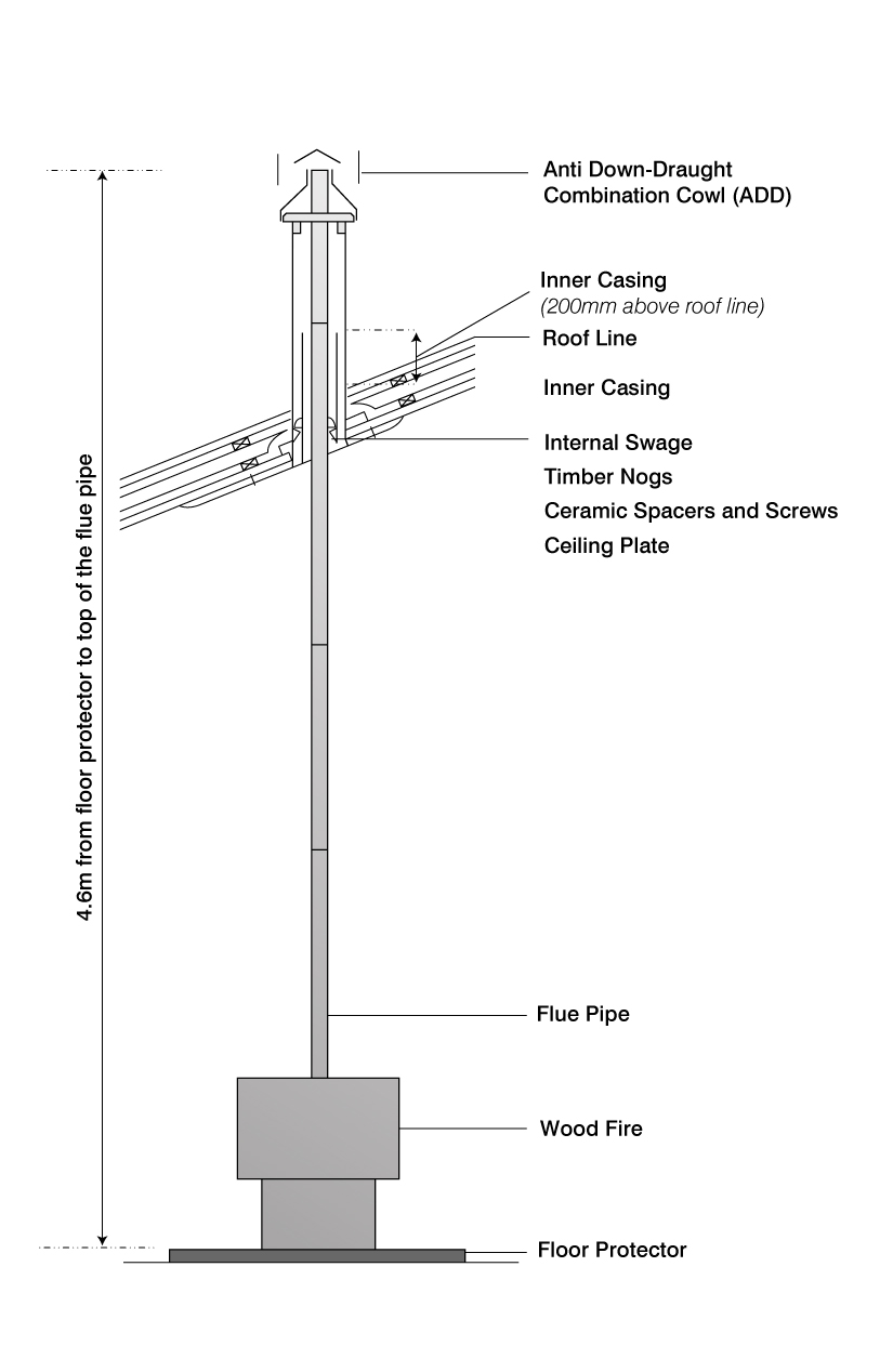
Note that AS/NZS 2918:2001 4.9.1(a) states, “the FLUE PIPE shall extend not less than 4.6m above the top of the floor protector.” Refer to diagram B.
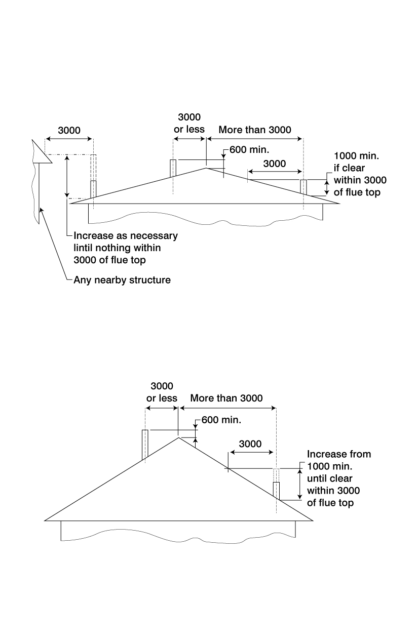
- If the FLUE PIPE is within 3 metres of the ridge, the FLUE PIPE must protrude at least 600mm above the ridge of the roof.
- If the distance from the ridge is more than 3 metres, the FLUE PIPE must protrude at least 1000mm above roof penetration.
- The FLUE PIPE must be more than 3 metres from any nearby structure. (Refer to diagram C)
Additional FLUE PIPE, OUTER CASING and/or INNER CASING may have to be added to ensure the following:
- The correct minimum roof penetration height.
- Sufficient overall height to encase the FLUE PIPE which must extend a minimum of 4.6 metres from the floor protector. Refer to diagram B.
Note that the INNER CASING should extend 200mm above roof penetration.
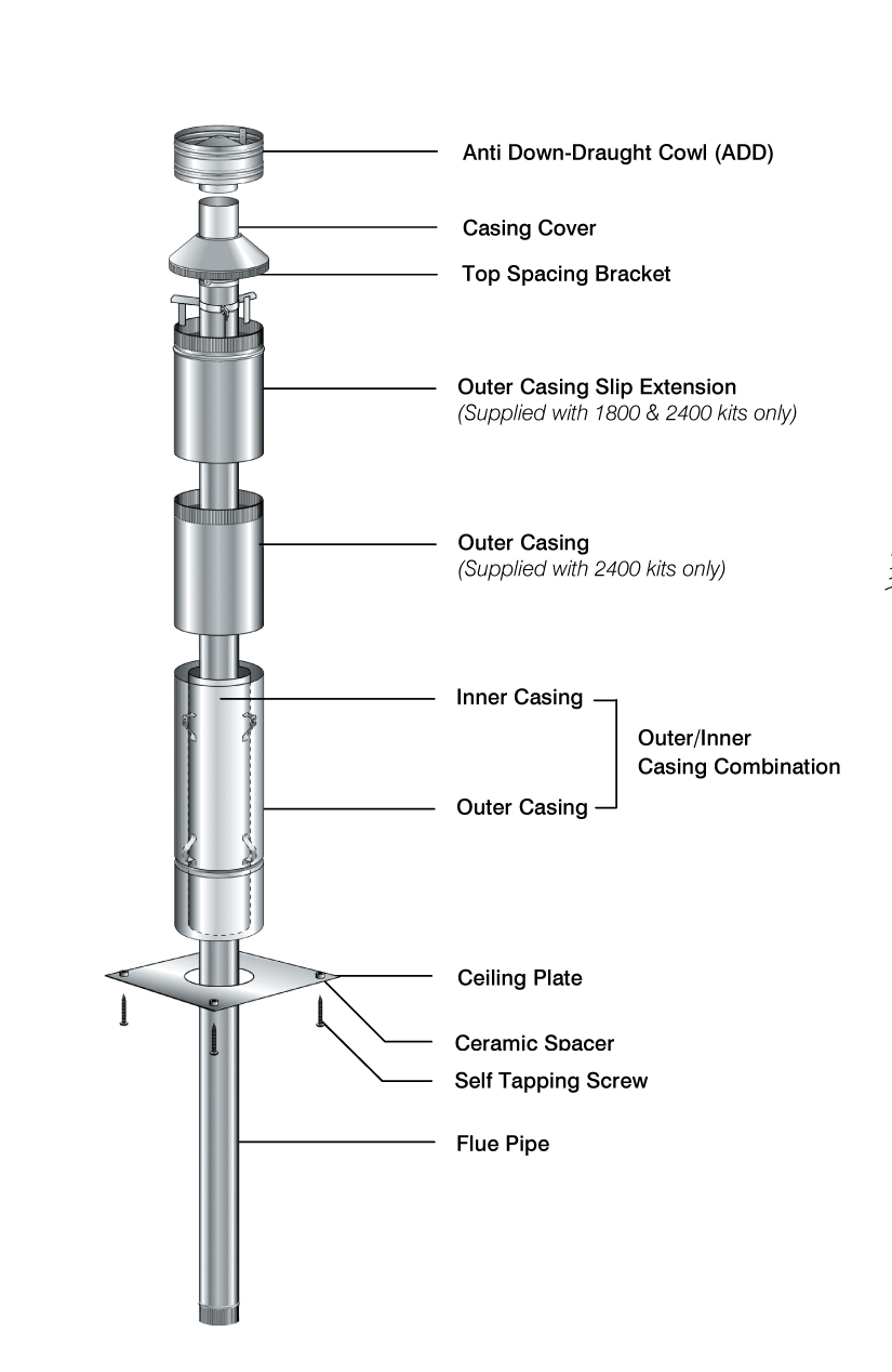
NB: Do not secure the OUTER CASING SLIP EXTENSION onto the OUTER CASING, as a final adjustment will be required when fitting cowl assembly. See paragraph 11.
- Fix an appropriate flashing around the OUTER CASING to seal onto the roofing material. Refer to the manufacturer’s recommendations for correct fitting. NB: On iron roofs, fixings such as metal angle, brackets (approximately 25 x 25) can be fitted under the flashing to securely fix the roof to OUTER CASING.
- Place SFP DROP CASING CONE on top of the Wood Fire.
- Position bottom length of FLUE PIPE (crimped end downwards) into Wood Fire Flue Spigot.
Refer to the supplier of Wood Fire and use flue pipe sealant if recommended.
- Assemble FLUE PIPES together ensuring seams are straight, offsetting the seams will ensure a neat fit. FLUE PIPES must be assembled with crimped ends down (towards Wood Fire). Secure each joint with a minimum of 3 Monel steel rivets equally spaced around the joint. If using HI-THERM FLUE PIPE the protective wrapping should be left on the FLUE PIPE during installation.
- From the roof lower FLUE PIPE through OUTER CASING into the bottom FLUE PIPE securing with 3 Monel rivets.
- Check that the FLUE PIPE SPACING BRACKETS inside the INNER CASING are correctly positioned and then from the roof slide the INNER CASING into the OUTER CASING until the brackets rest on to the internal swage ring of the OUTER CASING, this will ensure the INNER CASING is the correct 12mm above ceiling level.
Check the INNER CASING when correctly positioned extends a minimum of 200mm above the roof penetration.
- Before securing the OUTER CASING SLIP EXTENSION to the OUTER CASING with 3 rivets, ensure the FLUE PIPE extends above the top of the OUTER CASING SLIP EXTENSION 145mm. adjust SLIP EXTENSION to obtain this measurement.
- Fit TOP SPACER BRACKET to the FLUE PIPE making sure the lugs fit snugly inside OUTER CASING SLIP EXTENSION. Make sure TOP SPACER BRACKET fits hard down onto OUTER CASING SLIP EXTENSION.
- Fit CASING COVER over the FLUE PIPE and push down firmly onto TOP SPACER BRACKET.
- Fit COWL but do not secure, as removal for cleaning will be necessary. Deform or ovalise the stub of the COWL to ensure it is a tight friction fit.
- Fit the DROP CASING CONE to the end of the DROP CASING UNIT.
Leave all installation and operating instructions with the owner.
Stainless Steel pipe should be wiped clean using a soft cloth and methylated spirits to remove finger marks and oils used to manufacture the flue pipe.
Hi-Therm pipe can be touched up using only STOVE BRIGHT aerosol paint.