150mm Sloped E-Kit Option Installation
../Installation Guides/150mm Sloped Wood Fire Flue Kit Installation Guide
WARNING: THIS FLUE KIT HAS BEEN MANUFACTURED IN ACCORDANCE WITH AS/NZS 2918:200 AND TESTED TO APPENDIX F. TO ENSURE SAFETY THIS FLUE KIT MUST BE INSTALLED AS OUTLINED IN THE INSTRUCTIONS. WOOD FIRE AND FLUE PIPE CLEARANCES FROM COMBUSTIBLE WALLS MUST BE IN ACCORDANCE WITH WOOD FIRE MANUFACTURER'S SPECIFICATIONS AND AS/NZS 2918:2001. THESE INSTRUCTIONS ARE FOR TESTED APPLIANCES ONLY.
CAUTION: IT IS THE RESPONSIBILITY OF THE INSTALLER TO ENSURE THAT THE INSTALLATION OF THIS FLUE KIT COMPLIES WITH AS/NZS 2918:2001, THE APPLIANCE MANUFACTURER'S SPECIFICATIONS FOR FLUE PIPE SHIELD AND CEILING PLATE AND THAT THE RELEVANT BUILDING CODES ARE ADHERED TO.
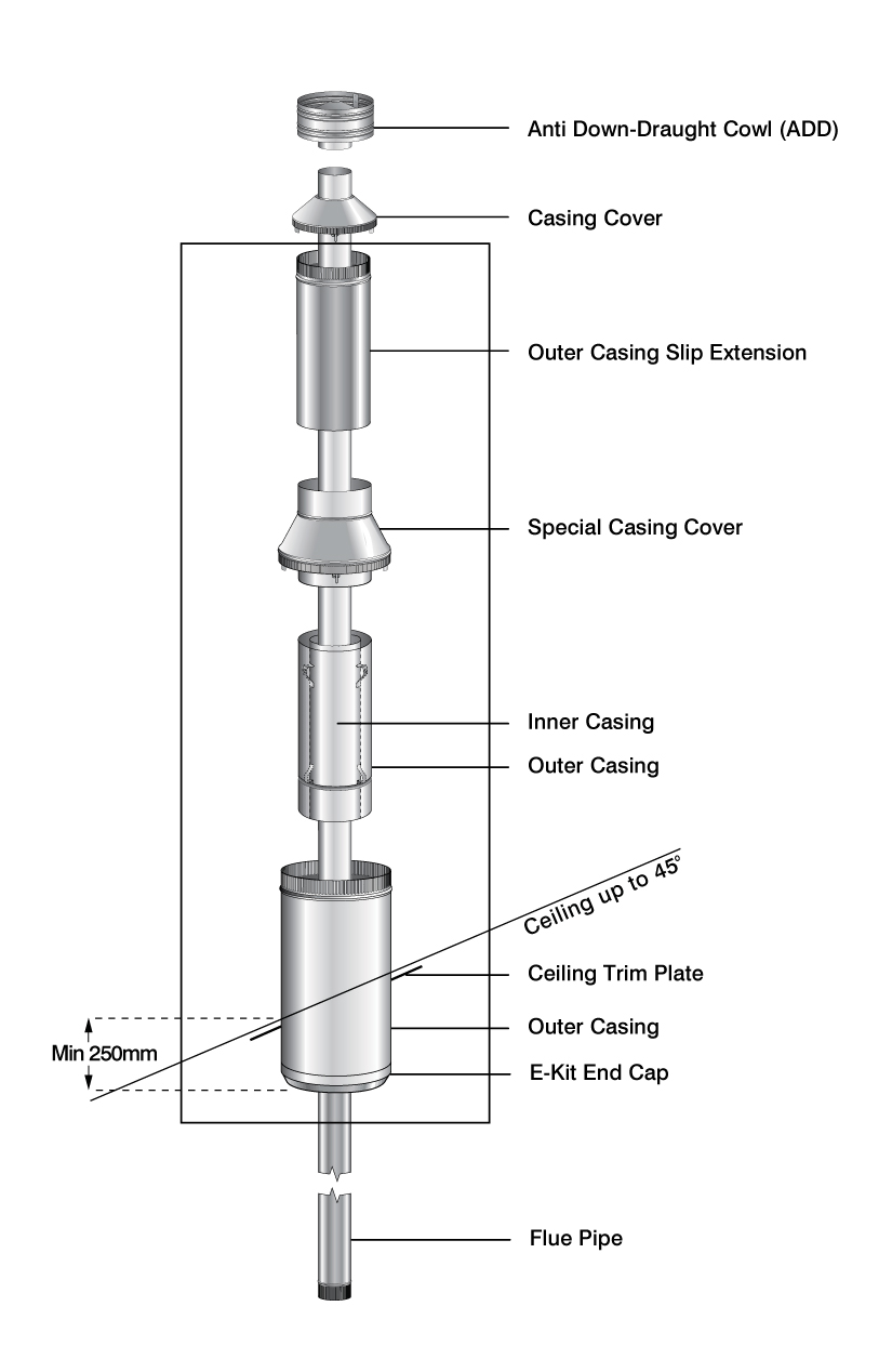
The 300mm OUTER CASING provides the support for the 250/200 OUTER/INNER CASING COMBINATION and 300/250 SPECIAL CASING COVER and OUTER CASING EXTENSION in the finished FLUE SYSTEM
To achieve the bracing required to adequately support the 300mm OUTER CASING in a Sloped Ceiling situation additional timber or metal framework may be required within or below the ceiling cavity and external bracing required on the roof.
- Locate Wood Fire in its proposed position and mark a point on the ceiling that is directly above the centre of the heater’s flue outlet. Check that the heater’s location allows 300mm OUTER CASING to clear all structural roof timbers.
- Cut a 300mm square hole in ceiling and roof cavity and construct an adequate support structure for the 300mm OUTER CASING.
- Fit the 300mm OUTER CASING into the ceiling aperture securing with screws. The 300mm OUTER CASING should extend a minimum of 250mm below the underside of the ceiling (measured on lower or shorter side of penetration).
- Position the 250/200 OUTER/INNER CASING COMBINATION into the 300mm OUTER CASING ensuring it locates into the square SUPPORT FRAME at the bottom of the 300mm OUTER CASING. The OUTER/INNER CASING COMBINATION will protrude through the 300mm OUTER CASING at the required height to be supported by the 300/250 SPECIAL CASING COVER.
- Fit an appropriate flashing to the 300mm OUTER CASING to seal onto the roofing material. Refer to the manufacturer’s recommendations for correct fitting.
- Fit the 300/250 SPECIAL CASING COVER (with lower spigot outside 250/200 OUTER/INNER CASING COMBINATION) onto the 300mm OUTER CASING. The 4 location brackets with holes must be on the outside of the 300mm OUTER CASING and secure using fasteners.
- Fix the 250mm OUTER CASING SLIP EXTENSION to the 300/250 SPECIAL CASING COVER. The FLUE PIPE outlet will be 145mm above the top of the 250mm OUTER CASING SLIP EXTENSION so the height from the top of the FLOOR PROTECTOR to the top of the 250mm OUTER CASING SLIP EXTENSION should be determined to ensure compliance to AS/NZS 2918:2001 4.9.1(a) Note: AS/NZS 2918:2001 4.9.1(a) states, “The FLUE PIPE shall extend not less than 4.6m above the top of the floor protector.”
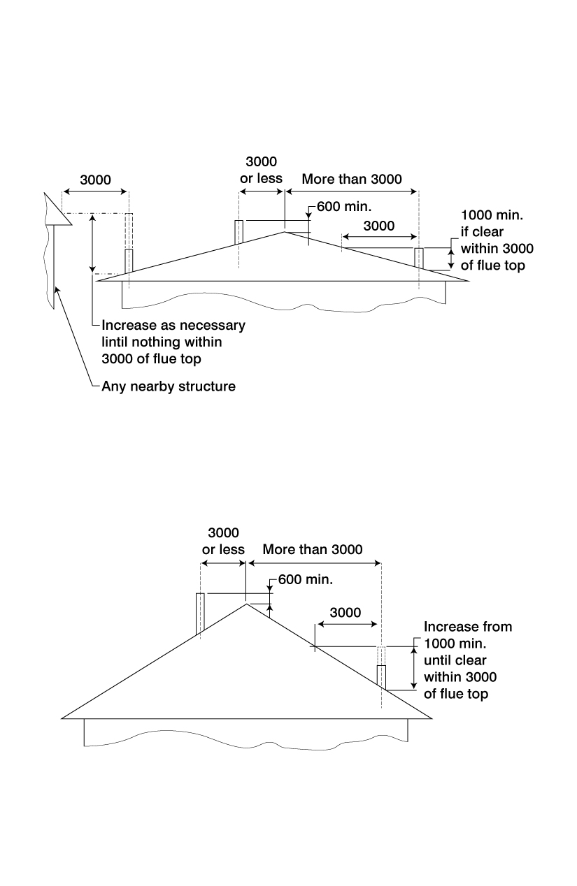
- If the FLUE PIPE is within 3 metres of the ridge, the FLUE PIPE must protrude at least 600mm above the ridge of the roof.
- If the distance from the ridge is more than 3 metres, the FLUE PIPE must protrude at least 1000mm above roof penetration.
- The FLUE PIPE must be more than 3 metres from any nearby structure.
-
Fit SLOPED CEILING TRIM PLATE to ceiling.
-
Position bottom length of the FLUE PIPE (crimped end downwards) into heaters flue outlet.
-
Refer to the supplier of the heater and use flue pipe sealant if recommended.
-
Assemble FLUE PIPES together ensuring seams are straight; offsetting the seams will ensure a neat fit. Secure each joint with 3 rivets equally spaced around the joint. FLUE PIPES must be assembled with crimped ends down (towards heater). If using HI-THERM FLUE PIPE, the protective wrapping should be left on the FLUE PIPE during installation.
-
Place 305mm E-KIT END CAP over heater’s flue spigot.
-
From the roof lower FLUE PIPE through OUTER CASING into position.
-
Carefully fit 305mm E-KIT END CAP to lower end of 300mm OUTER CASING.
-
a) If fitting FLUE KIT with TOP SPACER BRACKET:
- Ensure the FLUE PIPE extends above the top of the OUTER CASING EXTENSION by 145mm cut either OUTER CASING EXTENSION or the FLUE PIPE to obtain this measurement.
- Fit top SPACER BRACKET to the FLUE PIPE making sure the lugs fit snugly inside OUTER CASING EXTENSION. Make sure TOP SPACER BRACKET fits hard down onto OUTER CASING EXTENSION.
- Fit CASING COVER over the FLUE PIPE and push down firmly onto TOP SPACER BRACKET.
-OR-
-
b) If fitting FLUE KIT with COMBINATION CASING COVER:
- Ensure the FLUE PIPE is either flush with or extends above the top of the OUTER CASING EXTENSION by no more than 15mm. Cut SLIP EXTENSION or FLUE PIPE to obtain this measurement.
- Push CASING COVER (with spigot inside FLUE PIPE) down onto the OUTER CASING SLIP EXTENSION. The 3 locating brackets with holes must be on the outside of the OUTER
- CASING SLIP EXTENSION and are secured using 3 rivets.
Fit COWL but do not secure, as removal for flue cleaning will be necessary. Deform or ovalise the stub of the COWL to ensure it is a tight friction fit.
Leave all installation and operation instructions with the owner
Stainless Steel pipe should be wiped using a soft cloth and methylated spirits to remove finger marks and oils used to manufacture the flue pipe.
Hi-Therm Flue Pipe can be touched up using only STOVE BRIGHT aerosol paint.