Floor Penetration Unit 150/200/250 Installation Instructions
../Installation Guides/Floor Penetration Unit 150/200/250 Installation Guide
WARNING: THIS FLUE KIT HAS BEEN MANUFACTURED IN ACCORDANCE WITH AS/NZS 2918:2001 AND TESTED TO APPENDIX F. TO ENSURE SAFETY THIS FLUE KIT MUST BE INSTALLED AS OUTLINED IN THESE INSTRUCTIONS AND THE APPROPRIATE REQUIREMENTS OF THE RELEVANT BUILDING CODE OR CODES. WOOD FIRE AND FLUE CLEARANCES FROM COMBUSTIBLE WALLS MUST BE IN ACCORDANCE WITH WOOD FIRE MANUFACTURER'S SPECIFICATIONS AND AS/NZS 2918:2001. THESE INSTALLATION INSTRUCTIONS ARE FOR TESTED APPLIANCES ONLY.
CAUTION: IT IS THE RESPONIBILITY OF THE INSTALLER TO ENSURE THAT THE INSTALLATION OF THIS FLUE KIT COMPLIES WITH AS/NZS 2918:2001, AND THE APPLIANCE MANUFACTURES SPECIFICATIONS FOR CEILING/WALL PLATE AND THAT THE RELEVANT BUILDING CODES ARE ADHERED TO.
CAUTION: MIXING FLUE SYSTEM COMPONENTS FROM DIFFERENT SOURCES OR MODIFYING THE DIMENSIONAL SPECIFICATIONS OF COMPONTENTS MAY RESULT IN HAZARDOUS CONDITIONS. WHERE SUCH ACTION IS CONSIDERED, THE MANUFACTURER SHOULD BE CONSULTED IN THE FIRST INSTANCE.
Bends and extensions to the length of a flue system are permitted (AS/NZS 2918:2001 4.1)
For heaters tested in accordance with AS/NZS 2918:2001 using a SFP type flue.
-
With the heater located in its proposed position mark a point on the first floor/ceiling that is directly above the centre of the flue outlet. Check that the heater’s location allows FLOOR PENETRATION UNIT to clear all structural floor timbers.
-
Cut a 255mm square hole in floor.
-
Measure length from surface of floor to ceiling below. Remove OUTER CASING EXTENSION on FLOOR PENETRATION UNIT and adjust length of INNER CASING EXTENSION so that overall length (measured from flange on unit) is 12mm shorter. Secure INNER CASING EXTENSION with 3 rivets.
-
Adjust length of OUTER CASING EXTENSION to equal floor penetration thickness and secure with rivets or self-tapping screws.
FLOOR PENETRATION EXTENSIONS must be used when fitting MESH SCREENS (AS/NZS 2918:2001 4.6.30)
-
Fit FLOOR PENETRATION UNIT into the hole and secure with screws or nails through flange on unit into floor.
-
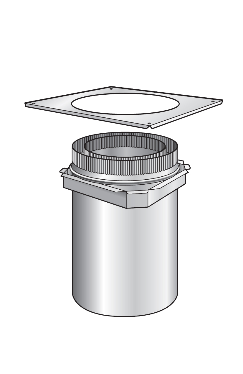
Drill (not necessary on pre-punched FLOOR TRIM PLATES) and fasten FLOOR TRIM PLATE to floor using self-tapping screws and spacers. Ensure an even air gap around OUTER CASING of FLOOR PENETRATION UNIT.
NB: 12mm air gap between floor trim plate and floor must be maintained.
-
Remove protective plastic from FLOOR TRIM PLATE (stainless steel plates only).
The FLOOR PENETRATION UNIT is now ready for the fitting of MESH SCREENS or OUTER CASINGS and the completion of installation of the FLUE KIT.
NB: for unprotected flue pipe installations or where MESH SCREENS will be fitted, the CASINGS must extend a minimum of 300mm ABOVE floor level. (Order separately from SFP to suit installation type).