Zero Clearance Gas Flue Kit Installation
../Installation Guides/Zero Clearance Gas Flue Kit Installation Guide
THIS FLUE KIT HAS BEEN MANUFACTURED IN ACCORDANCE WITH NZS 5261:1996. TO ENSURE SAFETY THIS FLUE KIT MUST BE INSTALLED AS OUTLINED IN THESE INSTRUCTIONS. HEATER AND FLUE PIPE CLEARANCES FROM COMBUSTIBLE WALLS MUST BE IN ACCORDANCE WITH HEATER MANUFACTURER'S SPECIFICATIONS AND NZS 5261:1996.
- Locate heater in its proposed position and mark the points for penetration that are directly above the centre of the heater’s flue outlet. Check that the heater’s location allows the OUTER CASING to clear all structural timbers.
- Cut 200mm square holes where penetration is required to accommodate OUTER CASING. NB: a minimum 25mm clearance is required between OUTER CASING and combustible surfaces.
- Fit timber nogs around holes where necessary.
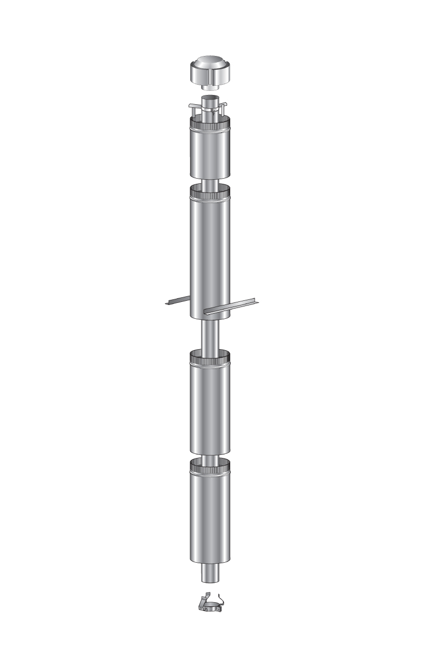
- Assemble OUTER CASING lengths together ensuring seams are in line and secure with 3 rivets or self-tapping screws. Lower OUTER CASING through roof or chimney structure and fit to heater spigot. Check height the OUTER CASING penetrates roof or chimney structure. When calculating roof penetration height allow for an extra 300mm that can be achieved by using the OUTER CASING SLIP EXTENSION.
The flue pipe is required to be at least 500mm above the nearest point on any part of the roof. It is recommended that in some instances extending the flue pipe above the ridge line will be necessary. Refer NZS 5261:1996 for more information. Additional CASINGS may have to be added to ensure the correct roof penetration heights are obtained.
- Assemble the 100mm stainless steel FLUE PIPES together ensuring all seams are in line using 3 pop rivets or screws and seal joints with appropriate sealant.
- Fit SPACER BRACKETS to FLUE PIPE if necessary to maintain air gap between FLUE PIPES and OUTER CASING.
- Lower Stainless Steel FLUE PIPES from the roof into the OUTER CASING (crimped ends
- Secure OUTER CASING to heater, if necessary.
- Using ANGLE BRACKETS secure OUTER CASING to nogs around penetration holes. NB: A minimum 25mm clearance is required between OUTER CASING and combustible surfaces.
- Fix an appropriate flashing around the OUTER CASING to seal onto the roofing or chimney material.
- Before securing the SLIP EXTENSION OUTER CASING to the OUTER CASING ensure the FLUE PIPE extends above the top of the SLIP EXTENSION OUTER CASING 25m. Adjust SLIP EXTENSION to obtain this measurement.
- Fix TOP SPACER BRACKET to the flue pipe making sure lugs fit snugly inside OUTER CASING.
- Fit GAS COWL into FLUE PIPE pushing down fully onto TOP SPACER BRACKET.
N.B: IT IS THE RESPONSIBILITY OF THE INSTALLER TO ENSURE THAT THE INSTALLATION OF THIS FLUE KIT COMPLIES WITH THE APPLIANCE MANUFACTURERS’ SPECIFICATIONS FOR FLUES AND TAT RELEVANT LOCAL BODY REQUIREMENTS ARE ADHERED TO.